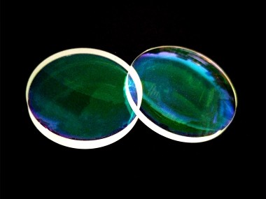
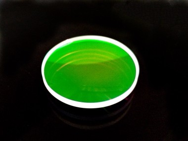
大尺寸的光学元件相对常规产品,其加工难度更大,检测更麻烦也相对不够准确。作为光学系统最核心的部分,炬科光学多年来一直在优化加工设备和工艺,总结了针对不同形状曲率的光学元件的多种方法,以提升检测精度为目的。目前炬科光学的光学透镜加工生产线,配备了2台ZYGO干涉仪和1台VEECO干涉仪,用于准确测量光学透镜的曲率半径和面形。
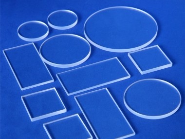
目前我们的检测直径范围可以达到200mm,曲率半径范围在±1000mm。我们始终致力于提供更可靠品质的光学元件,后续会计划配置更大口径激光干涉仪让检测的精度更加准确。

大口径激光干涉仪,通常是指口径在300mm(12英寸)及以上的激光干涉仪,大多数是卧式配置,也有用于特殊应用的立式配置。
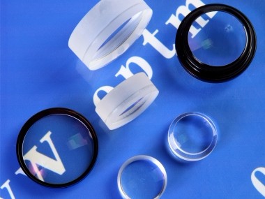
大口径激光干涉仪,自然主要用于“大口径光学元件”;包括表面面形,透射波前,材料光学均匀性等参数的测试。广泛应用于空间光学,强激光,同步辐射,光刻物镜制造等等核心项目。

ZYGO在大口径干涉仪领域的特殊优势在于:
ZYGO对于制造研发菲索式激光干涉仪,具有近50年丰富经验;产品和技术得到广泛认可。
光学加工也是ZYGO关键能力及核心业务之一。ZYGO大口径干涉仪系统中高精度标准镜,大口径扩束系统等等光学器件,全部自己设计和制造,确保了质量与交期,提高了性价比。
ZYGO长期深度参与以上提到的强激光NIF,空间光学NASA,光刻物镜等等国际核心项目,深刻理解这些关键应用的技术需求。
ZYGO大陆区域技术支持团队,有超过20年安装,调试,维护大口径激光干涉仪的经验。我们可以基于本地资源,安装,调试,维修包括800mm(32英寸)干涉仪,确保您的系统和相关项目能稳定高效地运行。

ZYGO大口径干涉仪双通道设计
ZYGO卧式大口径激光干涉仪,采用独特设计,可以分别在两个不同口径的通道上测量。包括干涉仪主机的100mm(4英寸)通道,及扩束后的大口径通道。(300mm,450mm,600mm,800mm可选)
根据样品的口径和尺寸大小;大口径样品在扩束通道测试,小口径样品可以在100mm主机通道测试,具有更好的适用性。使用主机通道测试小样品,提高了小口径样品测试的光学分辨能力。
ZYGO大口径干涉仪系统组件包括:
干涉仪主机 (Verifire™系列最高可选3.4KHDX或Dynafiz®)
MUX Cube 光路转换器
扩束器(300mm,450mm,600mm,800mm可选)
大口径机械移相器,适用于300mm(12英寸)和450mm(18英寸)系统;600mm(24英寸)和800mm(32英寸)使用ZYGO波长相位调制技术。
大口径透射标准镜,反射参考镜,大口径样品夹具及调整架。

ZYGO大口径干涉仪技术特点:
大口径标准镜的绝对标定技术 用于标定大口径平面标准镜的绝对面形,大幅提高系统面形测试的精度。
波长调制技术。ZYGO波长调制技术有了新的升级,可以和ZYGO QPSI™技术整合,有效减少环境振动对波长调制测试的影响。ZYGO新的波长调制技术对于测试“薄平行表面”的能力得到升级,最薄可以测试1mm光学厚度的前后平行表面样品。
ZYGO 推出了特有的基于ITF的自动对焦技术,对于关注PSD中频段测试的应用至关重要。
Ring Of Fire 环纹抑制功能,有效抑制异物,鬼像造成的环纹。
立式大口径干涉仪:
除了常见的卧式配置,ZYGO设计制造了立式配置的大口径激光干涉仪,满足特殊应用的需要。

300mm(12英寸)立式球面激光干涉仪
主要应用于半导体,光刻物镜项目,超高精度球面,非球面,平面光学器件面形及曲率半径测试。

用于立式检测大口径,超大口径平面样品表面形貌。借助拼接技术,它可以测试超过1m口径的平面样品。

ZYGO 300mm立式激光干涉仪
300mm(12英寸)立式激光干涉仪是ZYGO公司标准产品,用于立式姿态下,高效测试大口径平面样品表面面形。
微信公众号